DJI Matrice 100
Begin with a key video on the unboxing and setup of the DJI Matrice 100 quadcopter. Unlike consumer drones, the Matrice 100 requires considerable assembly once it’s unboxed, and it has many parts. The setup video guides you through step-by-step assembly of the parts, including bags of accessories. The Matrice 100 accepts different cameras. There’s a video on installing the gimbal and another on attaching a Z30 zoom lens camera. One video helps you link the remote controller to the aircraft.
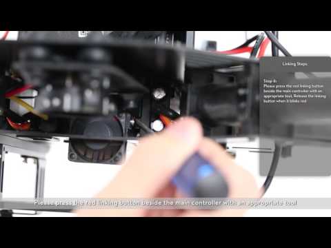
This video will show you how to link the Matrice 100’s controller to the aircraft. Please follow these steps. Connect the mobile device, turn on the remote controller. Turn on the battery. Run the DJI Go app on the mobile device. Enter the camera interface. Select RC settings. Select RC control settings. Select linking RC. The DJI Go app will initiate a countdown. The RC’s indicator will blink blue and make the following sound. Please press the red linking button beside the main controller with an appropriate tool. Observe the linking indicator behind the fan. Release the button when it blinks red. Linking is successful when the linking sound stops. Both the linking indicator and the RC indicator should turn solid green. Please contact DJI technical support if linking fails after several attempts.
Matrice 100 Tutorials - How to link the Matrice 100?s controller to the aircraft
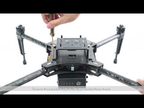
This video will show you how to mount the Zenmuse Z30 to the Matrice 100. To mount the Zenmuse Z30 make sure you have the following accessories: gimbal mounting board, rubber gimbal dampers, new upper central frame board, screws, extended landing gears. 2. Mounting the gimbal mounting board to the new upper central frame board. Detach the 2 screws on the new upper central board frame and remove the damper mounting piece. Mount the rubber gimbal damper to the mounting piece. Secure the screws on the new upper central frame board. Mount the other 2 rubber gimbal dampers on the gimbal mounting board to the corresponding holes. Gimbal mounting board installation is now complete. 2. Replacing the Matrice 100’s upper central frame board. Remove the GPS mounting base on the central frame board. Remove the expansion bay on the upper central frame board. Remove the aircraft status indicator at the rear of the upper central frame board. Remove the Matric 100’s upper central frame board. Pass the gimbal cable through the 2 reserved ports. Connect the 10PIN and 8PIN gimbal cables to the ports on the flight controller. Secure the new upper central frame board. Mount the aircraft’s status indicator. Mount the GPS mounting base. Mount the expansion bay. New upper central frame board is now complete.
3. Replacing the landing gears. Rotate the landing gear counter clockwise and remove it. Mount the extended landing gear and tighten it. Take care not to damage the antenna cover or antenna when mounting the landing gears. Attach the other 3 landing gears in the same fashion. Landing gear installation is now complete. 4. Mounting the Zenmuse Z30 gimbal. Ensure the aircraft is powered off before mounting the Zenmuse Z30. Remove the gimbal cover. Align the gimbal lock mark with the red dot on the lock and attach the gimbal. Rotate the lock and secure the gimbal. Gimbal installation is now complete. Please note that you should press the button on the left side of the gimbal mounting board and rotate the gimbal to unlock it before removing the camera.
Mounting the Zenmuse Z30 to the Matrice 100
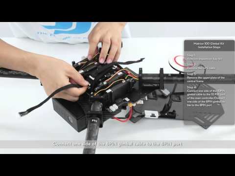
This video will show you how to install your Matric 100 gimbal kit. Please follow these steps. Frist remove the expansion bay kit. Remove the GPS cable. Remove the upper plate of the central frame. Connect 1 side of the 10PIN gimbal cable to the 10PIN port on the main controller. Connect 1 side of the 8PIN gimbal cable to the 8PIN port. Arrange the gimbal cables. Close the upper plate and tighten the screw with a screwdriver. Then connect the GPS cable to the designated port on the side of the central frame. Mount the mounting rails. Place the gimbal quick release part under the gimbal mounting plate and fix it with 4 cruciform screws. Connect the other side of the 8PIN gimbal cable to the 8PIN port of the gimbal buckle. Connect the other side of the 10PIN gimbal cable to the 10PIN port. Connect the gimbal mounting plate to the mounting position on the central frame’s upper plate via 4 vibration absorbers. Place the gimbal on the gimbal quick release port and attach it. The installation is complete.
Matrice 100 Tutorials - Gimbal Kit Installation
This video will talk about Matrice 100 unboxing and setup. Unboxing checklist. Your Matrice 100 box should include the following items: 1 remote controller, 1 battery, 1 gimbal mounting plate, accessories pack, 1 GPS accessories pack, expansions bay and mounting rails flashboard, 1 center frame arms M1-M4, propellers. Please check the list and ensure there are no missing items. Please setup your Matrice 100 with the following steps: 1. Remove the battery compartment and upper plate. First use the screwdriver in the accessories pack to remove the 4 screws on the battery compartment. Remove the battery compartment. Next remove the 8 screws on the mounting rails on the canter frame of the upper plate. Remove the upper plate of the center frame. 2. Mounting frame arms M1-M4. Insert the M1 frame arm into the corresponding slot on the frame. Make sure that it’s pushed in all the way. Attach the 3 degree fastener onto the outer arm slot of the center frame and ensure the arrow on the 3 degree fastener is pointing upwards. Adjust the fastener on the frame arm until it fits perfectly. Then tighten the 2 screws to hold it in place. Finally tighten the screws of the inner fastener. The installation of frameM1 is complete. Using these steps mount the other frame arm. Make sure frame arms M1-M4 are in the correct position.
The 0 degree fasteners can be mounted instead so that the motors in the fuselage are at a 0 degree incline. Please follow the same installation steps for the 3 degree fasteners when mounting the 0 degree fasteners. Note the pack contains both 0 degree fasteners and 3 degree fasteners. To obtain better flight performance we recommended using the 3 degree fasteners. 3. Mounting the frame arm cables. First connect the motor cables of each frame arm to the port of its corresponding ESC. Be sure to match the color of the cables and ports. Then connect the LED cable to each frame arm to the port of its corresponding ESC. Pull the antenna cable of the M1 through the cable tie on the lower plate of the center frame. Connect the M1 antenna cable to the corresponding antenna port on the bottom of the flight controller. Using the same method connect the antenna cables of the frame arm M2-M4. After connecting the antenna cables please tighten the cable tie to prevent the antennas from coming loose.
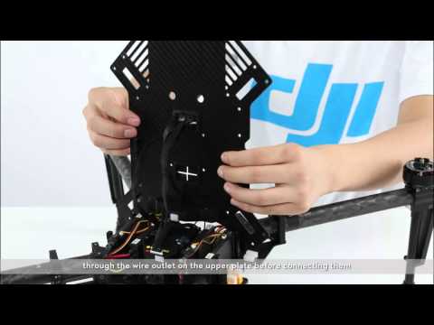
4. Mounting the upper plate of the center frame. Arrange the ESC light antennas and flight controller cables as shown here. Mount the upper plate on the center frame. Use M2.5*5 screws to attach the upper plate onto the aircraft. Mount the mounting rails above the upper plate using M2.5*8 screws. Adjust the slotted side of the upper plate of the center frame when mounting the upper plate of the center frame. Orient the upper plate so that the notch faces the left of the aircraft. Installation is complete. Notice: if you have the gimbal accessories kit you should connect the gimbal cables before mounting the upper plate and arrange the gimbals as shown here. If you need to adjust the position of the battery component from the top of the center frame to the bottom of the center frame. Pull the red green and white cables on the lower plate through the wire outlet on the upper plate before connecting them. 5. Installing the battery compartment. Mount the battery compartment onto the holes for the mounting rails. Tighten the screws. Open the battery compartment’s protective cover. Connect the various cables on the lower plate to the corresponding ports on the battery compartment.
If mounting the battery compartment above the center frame you can choose 1 of the 3 reserved positions to adjust the aircraft’s center of gravity. The cable ports will only accept the appropriate cables. If cables not correspond to their intended ports the cables cannot be connected to the ports. The 6PIN port with a yellow sticker is reserved. Do not connect any cables to this port. Pass the battery compartment’s power cable through the wire outlet on the battery compartment’s protective cover. Close the protective cover. Connect the battery compartment’s power cable to the XT60 port on the aircraft. Tighten the screws on the battery compartment. The installation is complete. 6. Mounting the expansion bay set. Slide the expansion bay base plate into the slots on either side of the plates. Tighten the screws. Place the expansion bay onto the mounting rails. Line up the holes on the expansion bay with the holes on the mounting rails. Tighten the screws. The installation is complete. 7. Mounting the GPS module. Apply glue to the hole at the GPS module base. Mount the bracket of the GPS module. Mount the collapsible GPS mount onto the designated position on the upper plate of the center frame. Tighten the screws on the mount. Use 3M glue to mount the GPS module onto the collapsible mount. Ensure the arrow of the GPS module points to the nose of the aircraft. Connect the GPS cable to the GPS port on the side of the center frame. The installation is complete. 8. Mounting the battery and propellers. Insert the battery into the battery compartment. Attach the propellers with white dots onto the motors white dots and tighten them. Attach the propellers without dots onto the motors without dots and tighten them. The setup of Matrice 100 is complete.
Matrice 100 Tutorials - Matrice 100 unboxing and setup
